honeywell control module wiring diagram
Page 58 5167798-YTG-J-0218 Typical CPC BAS Control Wiring Diagram Johnson Controls Unitary Products. WiringCoaxial Cable When repairing a wire that has broken from its terminal remove all old solder and pieces of wire from the terminal restrip the wire to the necessary length and resolder the wire to the terminal.

New Wiring Diagram Fender 5 Way Switch
The vehicle internetwork comprises specific devices software and protocols and provides for security for essential vehicle functions and data communications ease of integration of new devices and services to the.
. Such hyperlinks are provided consistent with the stated purpose of this website. PLC generally works on a 24V DC supply. The received data should be displayed on Port A.
Typical HONEYWELL BAS Control Wiring Diagram. Sequence diagrams Instrument loop specifications Local and control room panel layout drawings. The Honeywell gas control valve can be easily installed and is designed to fit all reliance standard natural gas water heaters with a Honeywell operation.
1 Installing the equipment interface module EIM Terminal Designations Conventional System Heat Pump. Typical NOVAR BAS Control Wiring Diagram. Vehicle internetworks provide for communications among diverse electronic devices within a vehicle and for communications among these devices and networks external to the vehicle.
It converts the available AC power to DC power which is required by the CPU and IO module. Although the DTIC may or may not use these sites as additional distribution channels for Department of Defense information it does not exercise editorial control over all of the information that you may find at these locations. Here are some additional values each of which can be used or omitted in any combination unless otherwise noted and except where prohibited by law and their meanings symmetry transitivity and inverse if any.
Few PLC uses an isolated power supply. If you use the former run the wire through the hole and place the fan bracebeam mount on the beam while supporting it with your hand. Another possibility is a low battery if the system is wireless but it should tell you this.
Instruments hook up drawing Cause and effect diagramESD logic test. You need to source the manual for the specific brand of control panel to see what the 403 code refers to. If you are installing discharge and return air sensors refer to the mounting instructions in the Alerts and Delta T Diagnostics Installation Instructions packed in the kit.
This module is used to provide the required power to the whole PLC system. The entire display. Constructed of T1-40 aluminized steel for enthalpy control that feeds input into the basic module.
Wiring Diagram Harbor Breeze Celing Fan With Light And Remote. Page 90 Disconnect the socket connector J2012 to separate the Front Panel Board from the display module. XFN 11 relationships meta data profile Authors.
HTML4 definition of the rel attribute. Able to understand and work on Ladder relay logic diagrams Loop wiring diagrams. CPU Module and Memory.
If the sensor is activating it could be due to faulty wiringloose connections or a faulty sensor if there was no problem previously. I have a portable fan that can use the power from an outlet to run the fan so it doesnt used the battery and charges it instead. Refer to the table and wiring diagrams on pages 3-5.
As described in HTML4 Meta data profiles. And S8670D in a variety of systems with alternate connections for modules with vent damper plug Dec 13 2010 The number of relays in a specific. The wiring of the XY-WA module is quite simple as it uses a direct SPI interface and a few digital pins.
CPU module has a central processor ROM RAM memory. The master is responsible for generating the clock signal used by the slave. Select the SPI product from the left column and the time scale from the top row.
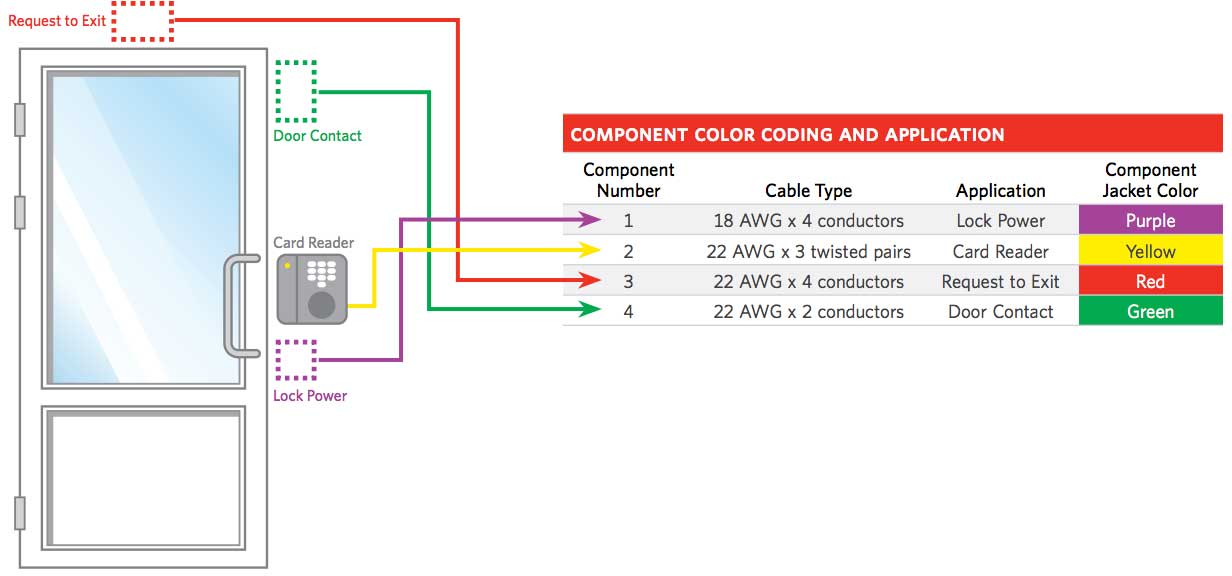
Access Control Cables And Wiring Diagram Kisi

Honeywell S8610u Wiring Diagram And Hires Jpg Tearing Diagrams New Throughout At Honeywell S8610u Wiring Diagram Diagram Wire Honeywell
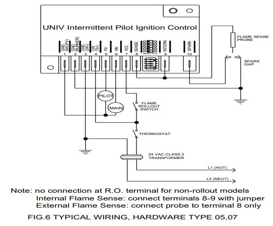
Series 5 Ignition Control Instruction Manual Capable Controls
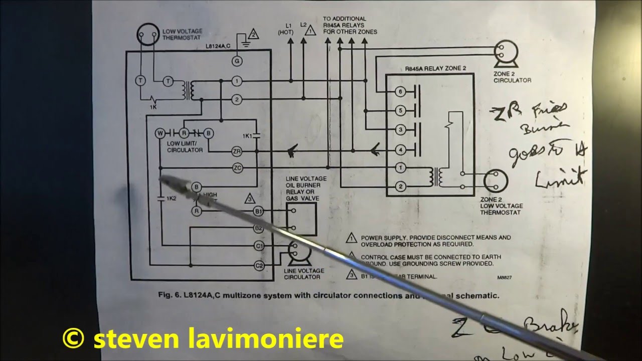
Boiler Aquastat Operating Control Wiring Explained Youtube

Gas Burner Primary Control Heater Service Troubleshooting

Gas And Temperature Control For Dummies Home Brew Forums Circuit Diagram Control Diagram
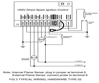
Series 5 Ignition Control Instruction Manual Capable Controls

Gas Burner Primary Control Heater Service Troubleshooting

Honeywell Ignition Control Am10xx Tm10xx Sch Service Manual Download Schematics Eeprom Repair Info For Electronics Experts Honeywell Repair Electronics

Wiring Diagram Connecting To An Hd Tv And A V Receiver For Video Tv Supportive Receiver
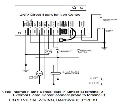
Series 5 Ignition Control Instruction Manual Capable Controls

Fire Alarm Horn Strobe Wiring Diagram Best Of Fire Alarm System Alarm System Fire Alarm
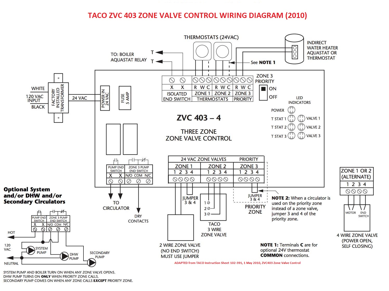
Zone Valve Wiring Manuals Installation Instructions Guide To Heating System Zone Valves Zone Valve Installation Inspection Repair Guide

Control Wiring New Basic Hvac Control Wiring Schema Wiring Diagram Thebrontes Co Unique Control Wir Arduino Stepper Electrical Diagram This Or That Questions

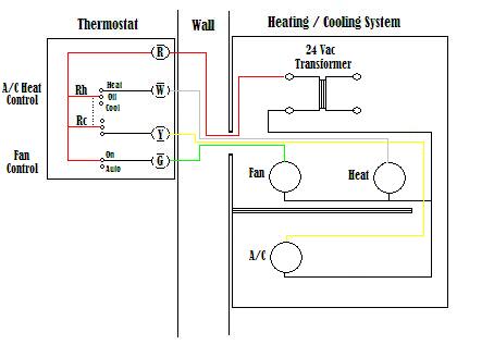
Carrier Hvac Thermostat Wiring Diagram Thermostat Wiring Hvac Thermostat Carrier Hvac
Wire A Thermostat

75 Hp Mariner Outboard Wiring Diagram Wiring Library
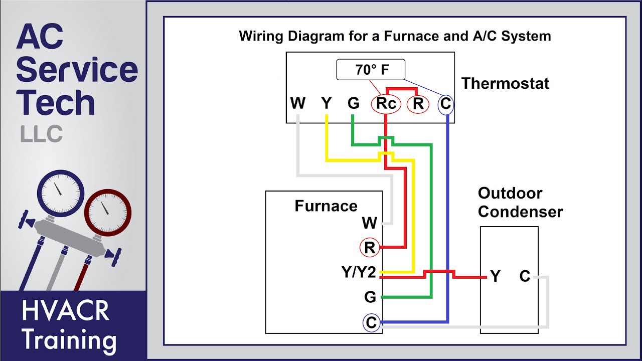
Thermostat Wiring To A Furnace And Ac Unit Color Code How It Works Diagram Youtube

Limit Switch Can T Find It If I Have One Heating Help The Wall